
It works!
UniBone proved its value even before prototype tests where complete:
Testbed was my work-horse PDP-11/34. Soon after first power-on, I noticed (quite frightened) that the first prototype had its "BG4" LED burning sometimes.
Of course the error vanished under debugging.
After checking UniProbe several times, resoldering the SMD op amps and suspecting THE BIG ERROR in the design, it turns out that a memory card had a bad backplane contact and was not able to close the Grant Chain reliably.
So the 11/34 indeed had a flaw, I never noticed this before!
Bottom line: Validating a new test instrument in a defective test bed can drive you crazy.
Use Patterns
As I started to work with my UniProbes, I almost instantly found me using two in parallel:
- The first one is build as M9302 terminator with LEDs for the Standard UNIBUS slot. It is only used to show the signals visually, and remains in place all the time.
- A 2nd one has only the logic analyzer interface populated and is plugged into the Modified UNIBUS on demand when working on a specific PDP-11. The LA cables remain plugged in all the time, the whole UniProbe is, well, the LA probe.

So if you have <n> PDP-11s , you probably need <n> UniProbes with LEDs and M9302, and 1 connected to your logic analyzer as flexible probe.
Getting One
In case you find UniProbe useful, I can provide them.
The PCB is a 4-layer with gold fingers.

To hand it over to you, multiple options were requested. Sadly in 2021 electronic components clearly increased in price. We now have:
- you download the schematic and the Gerber files for own production (no hazzle for me and all for you!)
- sending the blank board and the electronic parts (including pin headers and LEDs) as kit. Can do that for 130€, shipping to U.S. will be > 16€.
- a kit for the "two board" use case above. Two bare boards, and parts for the "LED+M9302" and a "LA-probe only" setup: €220.
- a ready-build and tested is 220€. The LEDs will be mounted as shown below: looking "sideways".
Other ideas?
Build variants
The UniProbe PCB can be populated to run either in the "Standard UNIBUS" socket or in the "Modified UNIBUS" socket ... but not in both! (Also see here).
Differences between variants are these:
| PCB section | Build variant | |
| "StdUB" | "ModUB" | |
| Solder jumpers (total of 15) | 1-2 ("up") | 2-3 ("down") |
| Front LEDs |
All LEDs operable. |
Grant LEDs BG*, NPG not connected. |
| Front voltage header J5 | Single row, only +5V and GND available |
Double row, |
| Logic analyzer interface | Grant signals BG*, NPG not connected. | |
| M930/M9302 terminator | For M930, open "M9302 SACK turnaround" jumper |
Do not populate: SIP resistors may be populated with high-Z (100K) to get defined levels for "open" UNIBUS signals, |
| Plug into Standard UNIBUS slot? |
OK | UNIBUS not properly terminated. Not all backplane GND pins connected Grant signals BG*, NPG not connected. |
| Plug into Modified UNIBUS slot? |
NEVER! |
OK |
Mounting LEDs
All LEDs should be visible when looking onto the card edge. Rotating them by 90° with a special 3D printed mounting block proved almost impossible to install. A more feasible solution does not rotate the LEDs, but just raises the 2nd row:


The small raisers (here painted black) are now part of the kits.
schematic-2019-03.pdf -- UniProbe schematic for version 2019-03
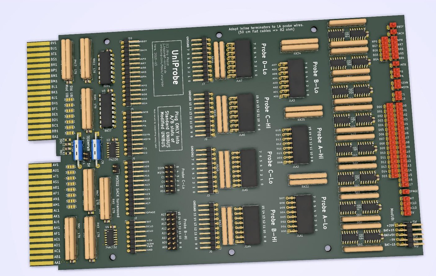
pcb-2019-03.jpg -- UniProbe PCB picture for version 2019-03
schematic-2019-02.pdf -- UniProbe schematic for version 2019-02